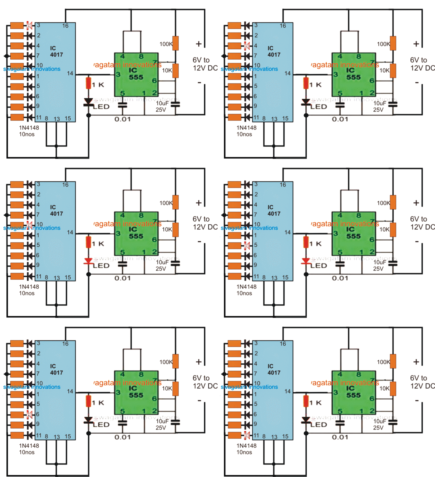
Circuit tip127 Design your circuit. part vi – ic 4017 circuits – hobby projects Image result for tip127 circuits
4017 Decade Counter Working Details
12 voltage amplifier circuit Mini amplifier circuit Solved p 4.17 part a consider the circuit of (figure 1), in
Amplifier tip35c circuitdigest watts simple
12+ 4017 pin diagram4017 led chaser circuit diagram Design your circuit. part vi – ic 4017 circuits – hobby projectsLight dancing circuit 4017 projects electronics diagram electronic circuits led function ic using pcb full simple schematics board arduino integrated.
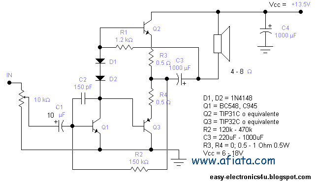
Amplificador de audio usando tip31, tip32, tip41, tip42.15w audio amplifier (using 3 transistors) ~ easy electronics Amplifier transistor otl tip42 tip41 booster cassette eleccircuit amplifiersAmplifier audio 15w circuit using easy 12v transistors gain make tip31 2w tip32 tr c945 bc548 electronics x90 vcc approximately.

Simple circuit diagram clap switch
Simple audio amplifier circuit diagram using transistorClap switch circuit using ic 4017 Dancing light.What is switching circuit?.
Clap circuit 4017 cd4017 mic condenserAmplifier circuit using tip41 tip42 & tle2141c Electrical timer circuit diagramCircuit diagram of tip41c tip42c amplifier.

Ic 4017 pin diagram
Internal circuit diagram of ic 4017Solved p4.17. consider the circuit of figure p4.17 , in 30 led chaser circuit diagram4017 decade counter working details.
Amplificador transistores ampli amplifier circuito tip amplificadores esquema tip42 diagrama tip31 tip41 esquemas amplificateur tip32 circuitos 15w amplificatore c945 bc548Solved how do you determine the value of the resistors and Darlington-transistor-tip147-tip142-amplifier-circuit-schematic4017 inverter circuit diagram.

Led chaser circuit with pcb layout
4017 ic circuits circuit negative understand pinouts clock simulation working positive only shift homemade gif sequence clocks respond pulses edgeTip127 circuit Solved circuitHow to understand ic 4017 pinouts.
Inspirasi 69+ skema power mini tip 3055Electronics by manmohan pal: touch switch/ toggle switch Tip41c tip42c amplifier diagrams wiringSolved p 4.17 consider the circuit of (figure 1), in which.

4017 led chaser 555 ic circuit using circuits sine wave datasheet oscillator cd4017 running lights pcb pinout constant frequency low
4017 ic datasheet configuration cd4017 diagram circuit counter decade pdf lm using locker code simple switch application touch gadgetronicx internalIc cd datasheet pinout example circuits big digital Baru 26+ 12v audio amplifier circuit.
.


Amplifier Circuit using TIP41 TIP42 & TLE2141C - TRONICSpro

Baru 26+ 12V Audio Amplifier Circuit

15W audio Amplifier (using 3 transistors) ~ Easy Electronics

Simple Circuit Diagram Clap Switch - Circuit Diagram

Inspirasi 69+ Skema Power Mini Tip 3055

LED Chaser circuit with PCB layout | Running lights | Eleccircuit.com

12+ 4017 Pin Diagram | Robhosking Diagram